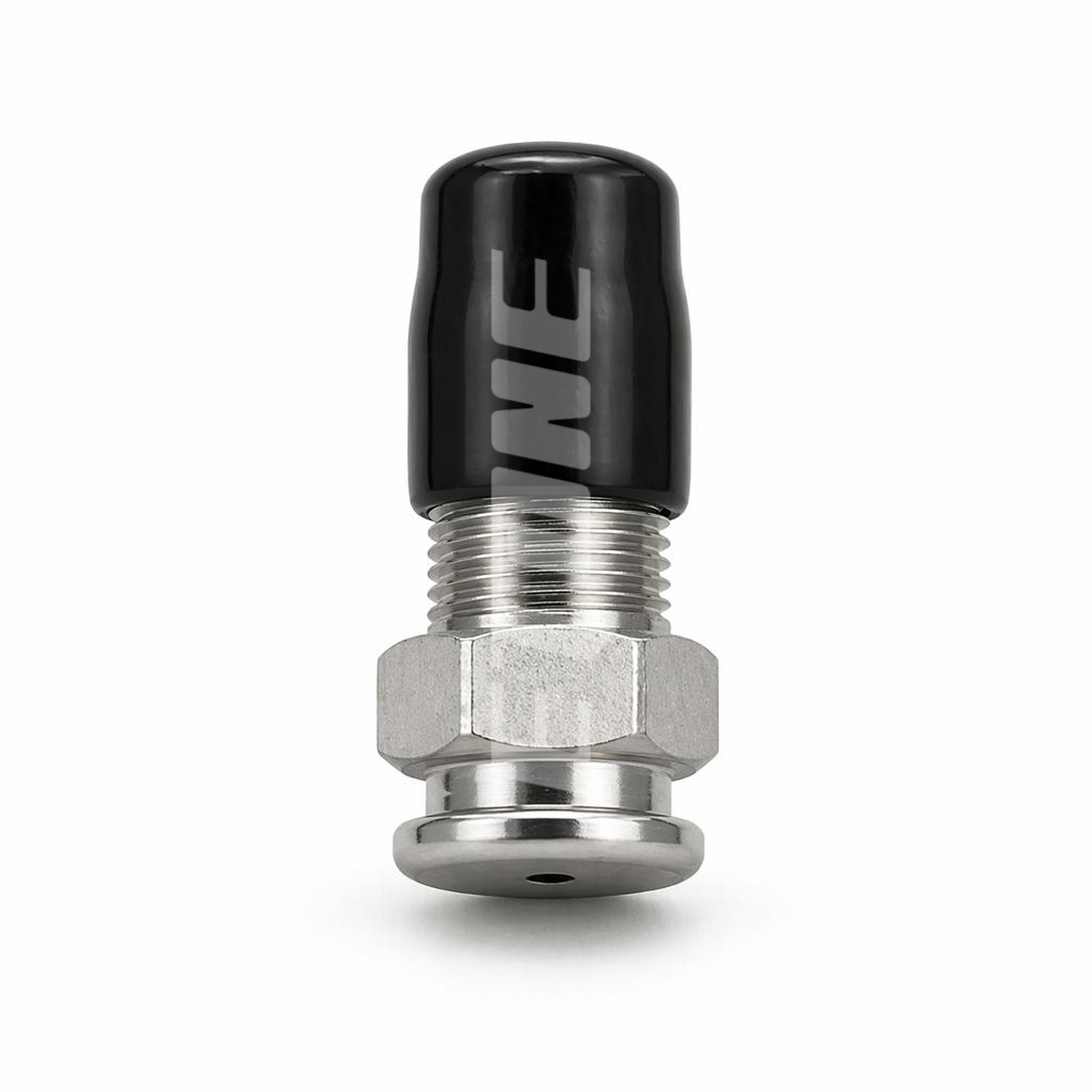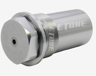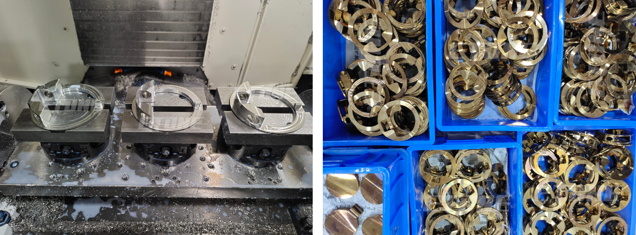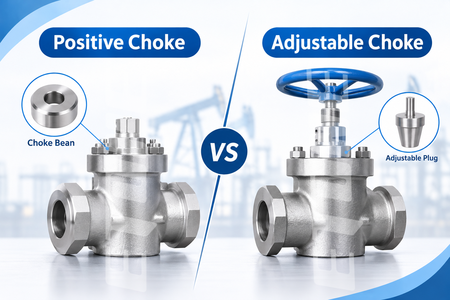
Choke beans are crucial components used in oilfield production and high-pressure flow control devices to control the flow of fluid. Located within a positive choke valve, a choke bean is a restricted opening that is designed to control the flow of oil, gas, and other production fluids.
While modest in size, the flow capacity, pressure drop, fluid velocity, and erosion resistance of the choke bean depend on the internal orifice geometry. The exact dimensions are critical; deviations can affect flow accuracy and downstream equipment efficiency.
Knowledge of how choke bean orifice geometry influences choke flow rate and pressure control is valuable when field operators are considering oilfield choke replacement parts to achieve maximum production.
1. What Is Choke Bean Orifice Geometry?
A choke bean serves as a replaceable flow-limiting element fitted within oilfield choke valves. The orifice, or central bore, is the main flow path for production fluids and controls flow throughput. Found in choke bean applications such as wellhead assemblies, production flowlines, well-testing skids, and hydraulic fracturing trucks, choke beans are designed for stable flow control through choke orifice geometry.
Important geometric features such as orifice diameter, which governs the free open flow area and therefore the flow capacity; orifice profile, which formulates the fluid entry, movement, and exit interior flow path; inlet and outlet configurations, which determine the degree of fluid contraction when entering and expanding when leaving the orifice and the associated turbulence levels; orifice length, which defines the flow loss and the flow characteristics inside the choking element; and surface finish, which reduces localized turbulence and increases wear resistance. All these features can make the choke bean effortlessly and confidently regulated at high-pressure fluid flow.
2. How Orifice Diameter Affects Flow Rate
Orifice diameter ranks among the critical specifications for oilfield choke bean selection. A bigger bore allows a greater volume of fluid to flow through the opening, while a smaller opening results in a greater restriction of flow. As long as the pressure differential and characteristics of the fluid don’t change, increasing the orifice size increases the effective flow area.
This cross-sectional area can be calculated according to the relationship: A = πD2 / 4, where A = orifice area and D = orifice diameter = 3.14 For this, one can see that the flow area increases with the square of the diameter. Using the 1/4″ orifice as a base reference, the relative flow area for 3/8″, 1/2″, and 5/8″ sizes are 2.25, 4.00, and 6.25, respectively.
Yet flow rate in practice is not always proportional to orifice area. For example, other factors such as pressure drop across the choke, oil or gas density, fluid viscosity, compressibility, and discharge coefficient also affect flow rate. Choke beans need to be correctly sized in oilfields to maintain production at the selected rate and not to induce damaging pressure transients.
3. How Orifice Shape Influences Pressure Drop and Flow Stability
In addition to orifice diameter, the flow control capabilities of choke beans are also influenced by the shape or profile inside the orifice. Each orifice type offers different internal flow characteristics.
The straight-bore orifice is the simplest of flow restrictions; a cylinder with a constant internal diameter. It is easily machined, simple to maintain and replace, and is therefore the most commonly used element for fixed standard restrictions. However, the liquid is accelerated due to the high differential pressure, and the downstream flow expands, causing turbulence and severe erosion.
In comparison, a tapered orifice has a varying internal diameter. A carefully designed (engineered) tapered bore provides a gradually tapering acceleration of fluid into the throat region rather than a sudden constriction. It can be designed to perform to a taper angle, throat diameter, surface finish, and operating conditions to suit a customer’s requirements.
Never forget, though, that the shape of inlet and outlet passages is important. Sudden changes in flow direction and flow separation from sharp edges will cause turbulence and an unnecessary pressure loss, whereas gradual curves will produce smooth redirection of flow. The optimum shape, of course, depends on the construction of the valve and the limits of throttling.
4. The Relationship Between Orifice Geometry and Pressure Control
A choke valve is primarily designed to establish a pressure differential across a restriction to flow. The passage of high-pressure fluid through the restriction’s smaller opening effectively accelerates the flow velocity within the restriction and, subsequently, decreases the pressure downstream of the restriction. This allows operators to manage wellhead pressure and production rates.
Pressure difference, Effective flow area, Discharge coefficient, and Fluid properties are some of the important parameters. The fluid flow rate and velocity in the orifice are mainly determined by the differential pressure between the upstream and downstream of the orifice. The orifice area is determined by the orifice diameter, which must be large enough to not excessively choke the flow or create an unbalanced pressure.
The simplified form of incompressible flow equations for Q, the volumetric flow rate, Cd, the discharge coefficient, A, the cross-sectional area, and ΔP, the differential pressure. Is the density of the fluid, which is used as the basic reference information for the engineer when calculating the flow. More extensive modelling has to be done for more complex configurations, including 2-phase or compressible gas or a choking state.
5. Poor Orifice Geometry and How it Causes Choke Bean Wear
In high-pressure oilfield service, the choke beans are continually flushed with abrasive solids, fluid impingement, and high differential pressures. Counterbore or inferior orifice shape accelerates internal erosion and flow control problems.
Unequal or unaligned orifices and bore sizes will have uneven flow delivery, which produces high velocity zones and increases erosion. The silica sand, ceramic proppants, and other grit in the fracturing and drilling fluids gently erode the bore surface. Choke beans of tungsten carbide are selected for such high abrasive conditions because of their greater hardness and wear resistance.
Operation in the liquid phase presents other unwanted phenomena. – Cavitation causes the formation of vapor bubbles when rapid localized drops of pressure occur. They collapse and cause the profile to become eroded and damaged. This problem can be avoided by carefully sizing the flow passage and controlling the pressure of the system. When the orifice is eroded and thus enlarged, the capacity will be increased. In this way, the flow rate will be greater than at the same valve setting. The pressure control will then no longer be stable and predictable.
6. Selecting the Appropriate Material for Various Choke Bean Uses
The flow path is set by orifice geometry; the survivability of a choke bean in the field is determined by the materials of construction. Tungsten carbide provides excellent hardness and abrasion resistance for high-pressure, sand-laden fluid service. Silicon carbide offers both very high hardness and good chemical resistance in some corrosive and abrasive conditions, but is very brittle, so is sensitive to impact loading, installation, and component design. Stainless steel offers a balance of corrosion resistance and machinability for low-abrasion applications, while alloy steel delivers the high mechanical properties needed for choke valve bodies and structural components. Choke valve bodies and structural components are made of alloy steel.
For high-performance oilfield choke beans, Tungsten carbide is still the primary material for high-velocity flow and abrasive solids. Analysis of service conditions such as pressure, temperature, fluid chemistry, and wear levels is essential for the material selected to guarantee a dependable service life.
7. How to Select High-Quality Choke Beans for Oilfield Operations
When sourcing replacement or custom choke bean components, buyers should look beyond nominal orifice size. Critical evaluation criteria cover orifice dimensions, including required bore size and tight tolerances; internal geometry, covering inlet, throat, outlet, and flow channel profiles; material grades such as tungsten carbide or silicon carbide matched to field conditions; full compatibility with your choke valve brand, model, mounting envelope, and connection specs; manufacturing accuracy, with reliable concentricity, stable bore dimensions, and fine surface finish; and quality documentation including dimensional test reports and material certifications. Assessment factors include orifice diameters, bore diameter specifications, tolerances; internal profiles, inlet, throat, outlet, and flow path profile considerations; grade of material used such as tungsten carbide or silicon carbide, hardness and field service compatibility; fully compatible with your choke valve brand, model, mount pattern, and connection requirements; tolerances of core piece concentricity, bore size, and surface finish quality; supply conditions, lead times, dimensional data, test certificates, material certificates.
Etone Oil offers positive flow choke beans in a variety of sizes and material options of tungsten carbide, silicon carbide, stainless steel, and alloy steel. Stock and OEM custom offerings are available for a wide range of oilfield choke valve applications.
8. Why Choose Etone Oil for Custom Choke Beans and Oilfield Spare Parts?
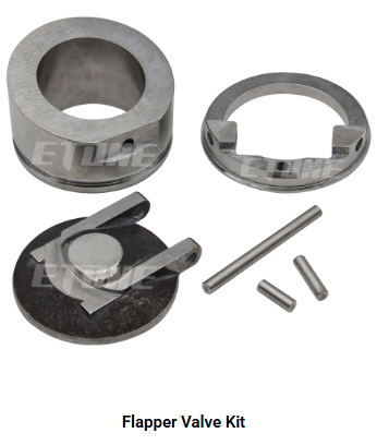
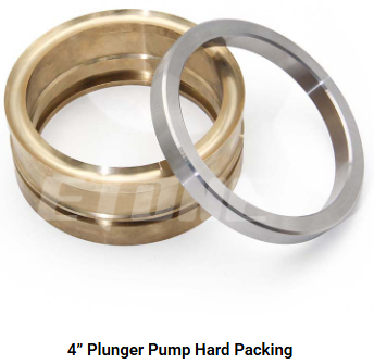
Dongguan Etone Tech. Co., Ltd. specializes in R&D, production, and customized manufacturing of precision machining parts and service kits for oilfield drilling equipment. We provide high-quality tungsten carbide and silicon carbide positive flow choke beans for high-pressure throttling, pluggable valve repair kits, back-flow control flapper check valve assemblies, relief valve service kits, plunger pump packing, as well as customized precision machined parts for drilling, cementing, completion, and fracturing jobs.
We use CNC turning and milling, Swiss machining, and 5-axis machining and work with materials such as AISI 4140, AISI 4340, SUS304, SUS316, 17-4 PH, special alloys, and tungsten carbide. The quality is checked in our own test lab certified to ISO 9001:2015 and IATF 16949:2016, and if you require standard positive flow choke beans or custom choke valve spares, our experienced team can check your drawings, samples, and technical specifications.
Website: https://etoneoil.com/
Phone / WhatsApp: +86 135 3728 5097