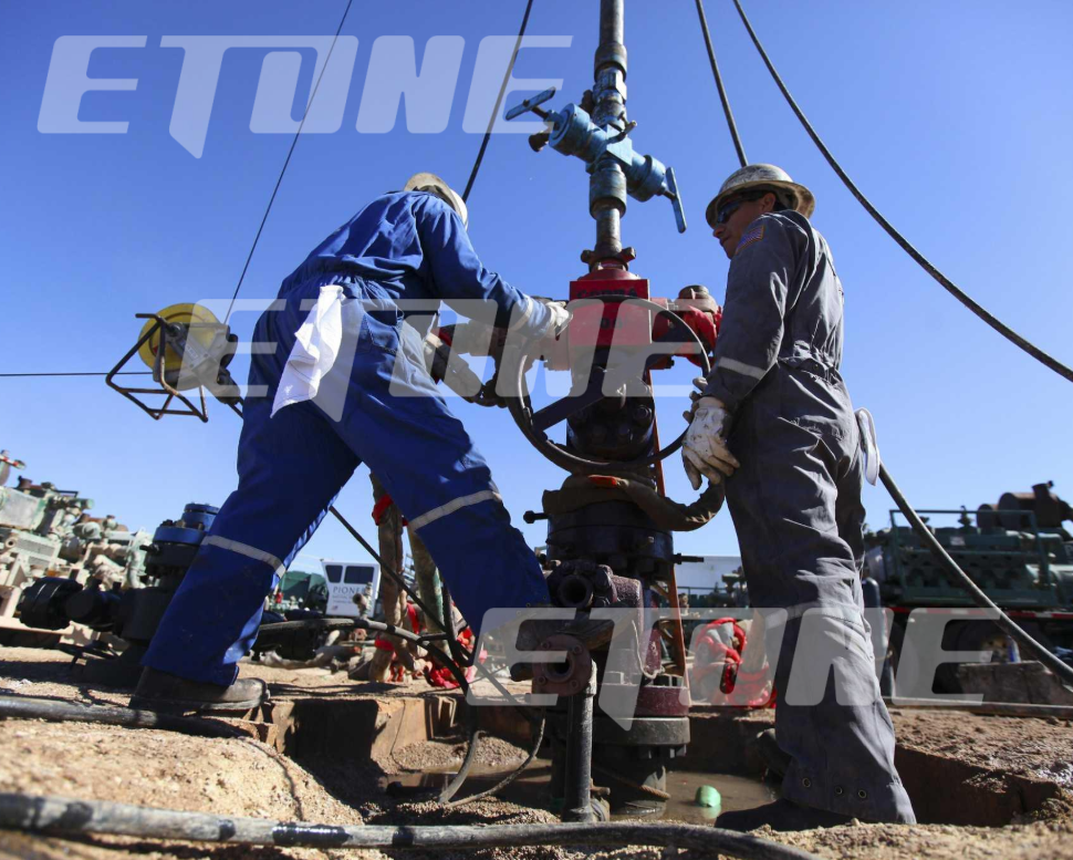
Within high‑pressure upstream oilfield activities such as well testing, hydraulic fracturing flowback, managed pressure drilling (MPD), and wellhead pressure management, choke valves serve as critical fluid‑throttling workhorses. Designed to function under extreme service pressures ranging from 5,000 PSI to more than 20,000 PSI, these valves control wellbore flow rates, stabilize backpressure, and reduce high upstream pressure to safe downstream levels.
Choke valves deliberately constrain high‑velocity fluids carrying silica frac sand, formation cuttings, drilling mud and corrosive gases, keeping internal parts under constant choked‑flow conditions. Sustained high fluid speed, large pressure differentials and harsh process media gradually trigger mechanical erosion, cavitation and thermal wear across internal components.
Internal damage to a choke valve brings instant operational repercussions: impaired pressure regulation, heavy seat washout, stem jamming, dynamic packing leakage, and unplanned Non‑Productive Time (NPT). For drilling contractors and well‑service operators, such unplanned downtime may incur hourly losses of tens of thousands of dollars.
Rather than replacing an entire forged valve body during an emergency shutdown, smart operators maintain their flowlines using high-precision oilfield valve spare parts. Installing premium replacement trims and repair kits restores factory-spec flow containment, prevents catastrophic washouts, and extends equipment operational lifespans at a fraction of the cost of new equipment.
This comprehensive technical guide details the most common choke valve problems encountered in well-service operations, provides step-by-step field troubleshooting protocols, and demonstrates how sourcing precision CNC oilfield valve spare parts from Etone Oil (www.etoneoil.com) maximizes operational uptime and drives purchasing efficiency.
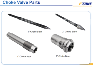
1. Anatomy of an Oilfield Choke Valve & High-Wear Components
To troubleshoot choke valve failures effectively, field engineers and maintenance crews must understand the internal component architecture of both positive (fixed) choke valves and adjustable choke valves.
A high-pressure choke valve assembly consists of outer pressure-containing housings and critical replaceable internal oilfield valve spare parts:
Valve Body & Bonnet
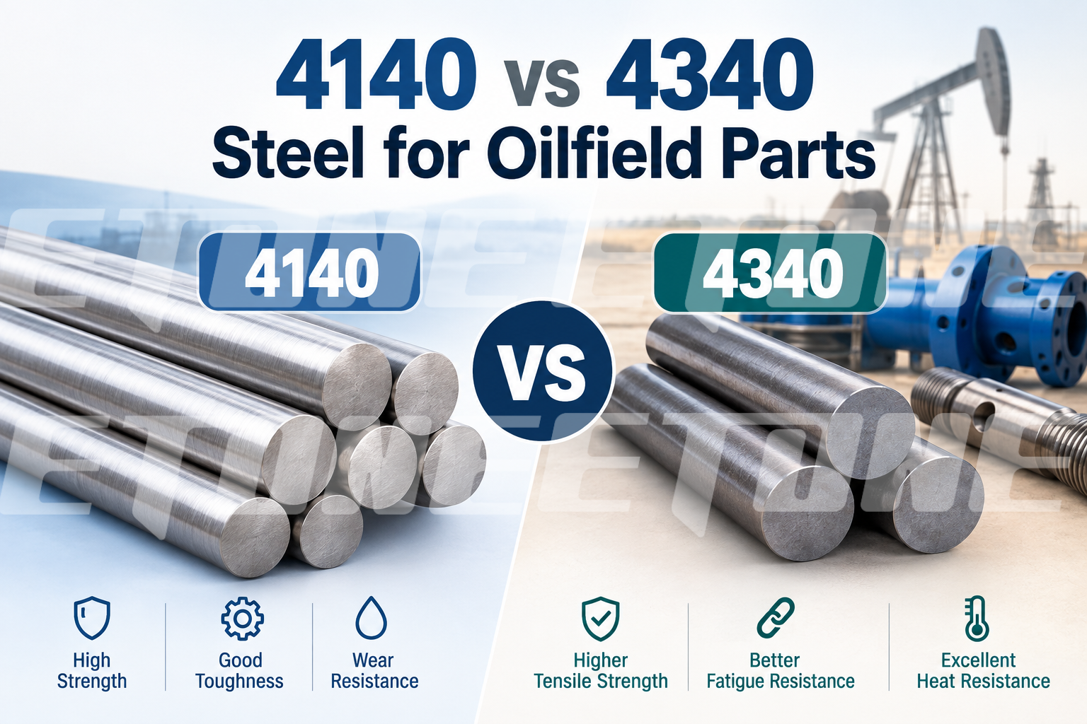
Forged from AISI 4130/4140 alloy steel and built per API Spec 6A, this outer housing comes with flanged or 1502 hammer union end connections.
Stem Needle (Adjustable Choke)
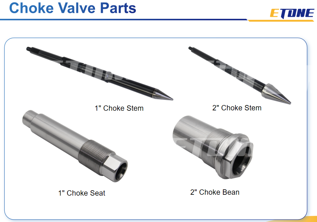
This heavy‑duty shaft features a solid tungsten‑carbide tip, either silver‑brazed or mechanically secured to the stem rod. Its forward and retracting movement modulates orifice clearance for flow regulation.
Seat Insert (Adjustable Choke)
A hardened steel sleeve internally lined with sintered solid tungsten carbide, it forms the mating throttling orifice that pairs with the stem needle.
Choke Bean (Positive Choke)
A swappable orifice insert protected by ceramic or solid tungsten‑carbide lining. Its dimensions follow 64ths‑of‑an‑inch sizing, with typical grades including #16, #24, #32 and #48.
Stem Packing Set
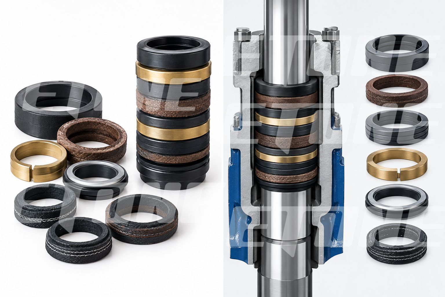
Multi‑ring chevron‑style V‑packing assemblies constructed from Kevlar‑reinforced HNBR, Viton (FKM) or PTFE, paired with PEEK backup rings. These components stop dynamic stem leakage even under pressures up to 15,000 PSI.
2. Problem 1: Orifice Erosion and Seat Washout
Symptom & Field Observation
During flowback or well testing operations, line pressure downstream begins to rise uncontrollably while upstream manifold pressure drops. Even when an adjustable choke valve is fully closed or tuned to a specific orifice setting, fluid continues to pass through. Physical inspection reveals deep longitudinal channels, pitting, or washouts across the tungsten carbide seat face or positive choke bean lining.
Root Cause Analysis
High‑Velocity Proppant Impact
Silica sand and ceramic proppant pass through the confined orifice at near‑sonic velocities, producing effects comparable to a high‑pressure sandblaster that damages valve internal surfaces.
Substandard Carbide Raw Materials
Generic, low‑quality oilfield valve spares built with poor‑grade binders or low‑density tungsten‑carbide suffer accelerated erosion when subjected to abrasive particle impacts.
Micro‑Gaps Within Seating Geometry
Non‑compliant machining tolerances create tiny clearances across seating surfaces. High‑pressure fluid shoots through these micro‑gaps in the form of micro‑jets, which quickly carve out erosive flow paths.
Solution & Preventive Action
Upgrade to Sintered Tungsten Carbide Trims: Always source high-performance Choke Valve Parts featuring premium sintered tungsten carbide from Etone Oil.
Precision Mirror-Ground Machining: Utilize oilfield valve spare parts ground to ultra-precise tolerances with a mirror surface finish to eliminate micro-gaps and prevent initial jetting.
3. Problem 2: Stem Binding and Hard Handwheel Turning
Symptom & Field Observation
Field operators find it extremely difficult or impossible to rotate the manual handwheel or actuate the choke stem needle. The stem feels stuck, jumps during rotation, or binds completely before reaching the closed position.
Root Cause Analysis
Thread Galling & Lack of Lubrication: The heavy Acme drive threads on the stem shaft or bonnet nut experience intense friction under high-pressure loads. Operating without specialized high-pressure grease causes thread galling and binding.
Proppant Ingress: Sand slurry enters the bonnet cavity through worn dynamic stem packing rings, packing into the drive threads and locking movement.
Bent Stem Shaft: Over-torquing the handwheel when clearing debris or severe lateral pressure surges bends the stem rod.
Solution & Preventive Action
Routine Greasing Protocol: Inject high-pressure synthetic grease into the bonnet grease fitting during every maintenance cycle.
Replace Worn Bonnet Internals: Replace damaged stem rods, bonnet nuts, and bearing sets using precision-cut CNC oilfield valve spare parts.
Upgrade Dynamic Stem Seals: Install fresh Kevlar-reinforced chevron V-packing sets from Etone Oil to prevent proppant and debris from migrating past the packing chamber into the drive threads.
4. Problem 3: Dynamic Stem Packing Leakage
Symptom & Field Observation
High-pressure well control fluid, oil, gas, or acidic water leaks out continuously around the rotating or sliding stem shaft under the handwheel/actuator bonnet nut.
Solution & Preventive Action
Extend Tungsten Carbide Sleeve Coverage: Install custom seat inserts and choke body liners featuring extended tungsten carbide sleeves that cover downstream expansion zones.
Optimize orifice structural design by adopting multi‑stage or cage‑guided choke trims from Etone Oil. These professional trims gradually reduce differential pressure in progressive stages, avoiding abrupt fluid pressure drops that fall below vapor pressure thresholds.
5. Problem 4: Sulfide Stress Cracking (SSC) in Sour Gas Service
Symptom & Field Observation
Alloy steel internal components, including valve stem rods, seat housings, and bonnet cap bolts, are prone to sudden fracturing or snapping under standard operating pressure, with no signs of preliminary plastic deformation.
Root Cause Analysis
In hydrogen sulfide (H₂S)-containing sour oil and gas well environments, free atomic hydrogen penetrates the lattice structure of high-strength steel materials. When subjected to tensile stress, the trapped hydrogen induces severe material embrittlement, triggering abrupt and destructive component failure defined as Sulfide Stress Cracking (SSC).
Solution & Preventive Action
Strict Compliance with NACE MR0175 / ISO 15156 Standards: To mitigate sulfide stress cracking in sour gas environments, all metallic valve replacement parts should receive qualified heat treatment to limit material hardness to ≤22 HRC, fully complying with standard anti-cracking requirements for field deployment.
Adoption of Inconel and Corrosion-Resistant Alloys: For extreme sour gas and acidizing service scenarios, Etone Oil offers high-performance choke valve components crafted from Inconel 718 and 17-4PH stainless steel. Each batch of these alloy parts is accompanied by official Material Test Reports (MTRs), delivering verified resistance to corrosion and sulfide stress cracking.
6. Step-by-Step Field Maintenance SOP: Overhauling an Adjustable Choke Valve
Follow this standardized 8-step field maintenance protocol to replace worn trims using fresh oilfield valve spare parts:
Step 1: Pressure Isolation & Safety LOTO
Verify that line pressure reads 0 PSI on upstream and downstream calibrated gauges. Lock-Out/Tag-Out (LOTO) isolation valves and open bleed ports to discharge trapped manifold pressure.
Step 2: Bonnet Disassembly
Unbolt bonnet studs in an alternating cross-star pattern using heavy-duty impact sockets. Carefully slide the bonnet assembly off the valve body.
Step 3: Removal of Worn Stem & Seat Trim
Extract the worn stem needle rod from the bonnet nut. Insert a dedicated seat removal tool into the valve cavity and unthread or pull out the worn tungsten carbide seat insert.
Step 4: Cavity Inspection & Cleaning
Solvent wash the internal valve housing bore to remove scale, proppant sand, and degraded grease. Inspect internal body walls for erosion channels using a bright LED work light.
Step 5: Installation of New Oilfield Valve Spare Parts
Retrieve a fresh Choke Valve Parts Kit from its sealed packaging.
Coat new HNBR / Viton O-rings and backup rings with synthetic valve lubricant and fit them onto the new tungsten carbide seat insert.
Push or thread the new seat insert into the valve cavity bore until fully seated.
Replace dynamic chevron V-packing rings inside the bonnet stuffing box.
Insert the new tungsten carbide stem needle shaft into the bonnet assembly, verifying smooth Acme thread engagement.
Step 6: Bonnet Reassembly & Torquing
Position the bonnet cap back onto the valve body. Thread bonnet studs by hand to prevent cross-threading, then torque bolts in a star pattern to manufacturer torque specifications using a calibrated torque wrench.
Step 7: Manual Calibration & Greasing
Inject dedicated synthetic valve grease through the bonnet grease port. Manually rotate the handwheel from full closed to full open stroke, and verify that the orifice position indicator delivers precise and accurate readings throughout operation.
Step 8: Hydrostatic Pressure Testing
Perform a dual-stage hydrostatic pressure test fully compliant with API Spec 6A standards to validate valve tightness and structural integrity.
Low-Pressure Seat Test: Sustain 250 PSI pressure for 5 minutes to confirm stable pressure holding and eliminate any seat bypass leakage.
High-Pressure Shell & Seat Test: Hold the full 15,000 PSI rated working pressure for 15 minutes, verifying zero leakage at valve seats, bonnet connections, and all pressure-bearing joints.
Source Certified Oilfield Valve Spare Parts from Etone Oil
Maintaining flowline pressure integrity requires reliable, precision-engineered replacement components. At Etone Oil (www.etoneoil.com), we manufacture a full range of high-precision oilfield valve spare parts, including:
Plug Valve Repair Kits: Heat-treated plugs, match-ground side segments, and HNBR seal rings for 1502/1002 plug valves.
Flapper Check Valve Repair Kits: Precision CNC flapper plates, hardened 17-4PH hinge pins, and fatigue-resistant springs.
Choke Valve Parts: Tungsten carbide stem needles, carbide seat inserts, and positive choke beans.
Relief Valve Repair Kits: Calibrated springs, stainless steel ground discs, and high-temp seats.
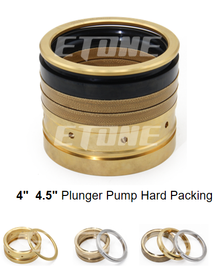
Plunger Pump Packing Sets: Kevlar-reinforced HNBR V-packing sets for triplex and quintuplex fluid ends.
Every replacement kit manufactured by Etone Oil undergoes 100% CMM dimensional checks, material traceability (MTR) verification, and pressure testing to ensure 100% drop-in fitment and long-term field reliability.
Partner with Etone Oil to streamline your replacement parts supply chain and eliminate unscheduled NPT.
Visit www.etoneoil.com today to explore our online catalog, download technical specifications, or contact our engineering sales team at pe@etoneoil.com for an immediate commercial quote within 24 hours.