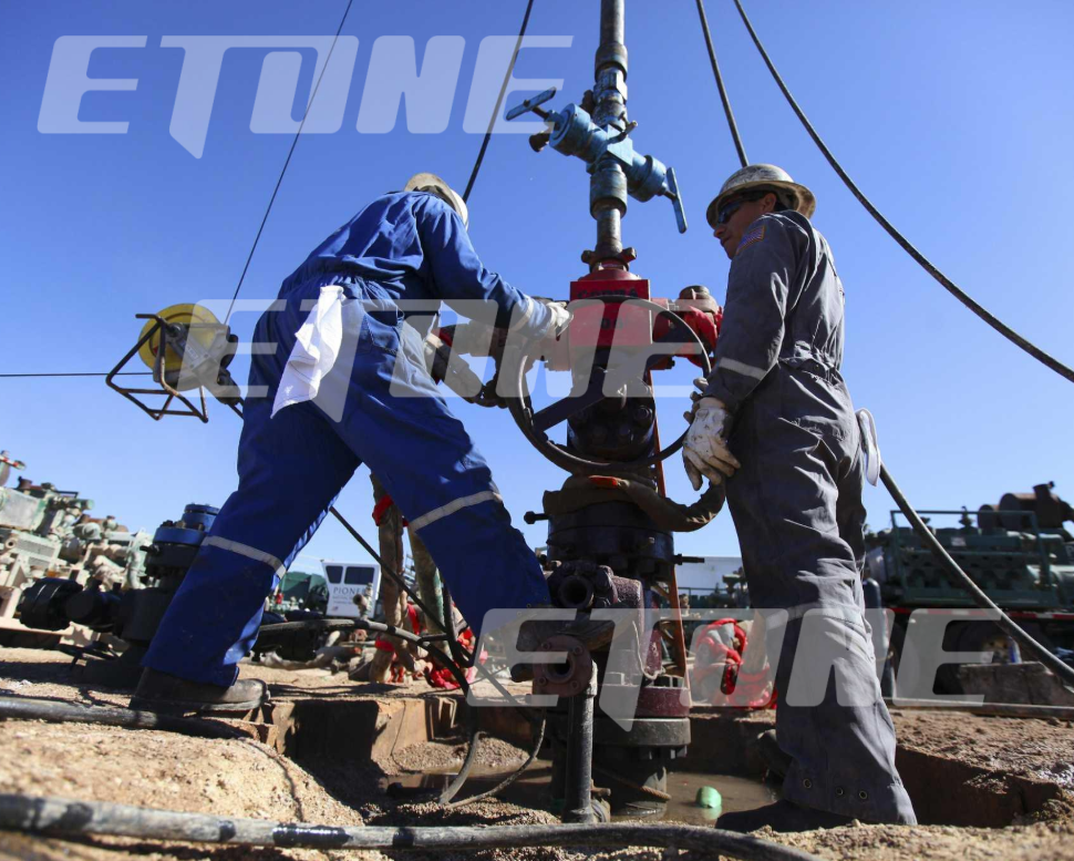
In high-pressure well-service and flow-line management—such as hydraulic fracturing, cementing, acidizing, and well testing—unidirectional pressure isolation is essential for operational safety. Located along high-pressure manifolds, discharge lines, and pumping connections, the Flapper Check Valve serves as a primary automatic safety barrier. Its main function is to allow high-velocity fluid to flow downstream while instantly sealing against reverse flow, protecting triplex/quintuplex mud pumps, frac units, and upstream manifolds from intense pressure backsurge and fluid hammer.
Operating under severe conditions—working pressures from 5,000 PSI to 15,000 PSI, abrasive proppant slurries, high differential pressures, and corrosive gases like hydrogen sulfide —internal wear components experience rapid mechanical degradation. Once an internal part becomes worn or its sealing‑contact profile drifts out of tolerance, the check‑valve can no longer achieve a full seal. This leaves upstream‑located equipment vulnerable to hazardous damage caused by backflow washouts.
Replacing the entire forged valve body during routine overhauls is unnecessary and costly. Implementing a proactive field maintenance schedule using a high-precision Flapper Check Valve Repair Kit restores pressure containment, extends equipment lifespan, and cuts Non-Productive Time (NPT).
This technical guide provides a step-by-step field maintenance procedure for inspecting, disassembling, overhauling, and hydrotesting high-pressure flapper check valves using precision CNC replacement parts.
1. Structure and Wear‑Prone Areas of High‑Pressure Flapper Check Valves
Maintenance engineers carrying out on‑site overhaul work need a clear understanding of the critical wear‑susceptible zones within high‑pressure flapper check valves.
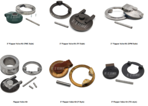
A full Flapper Check Valve Repair Kit comprises four core internal parts:
Flapper Plate (Valve Disc): The main sealing component rotating around a pivot axis. This part requires precision CNC machining to maintain flatness, enabling flush‑faced sealing against the valve seat.
Hardened Hinge Pin: A load‑carrying pivot shaft that bears the weight of the flapper plate during fast‑repeating pressure cycles.
Elastomeric Valve Seat & Body Seal Rings: Seal rings made of vulcanized HNBR, Viton (FKM), or Aflas are fitted into the valve‑seat bore to achieve bubble‑tight shut‑off across low‑pressure and high‑pressure service.
2. Pre‑Maintenance Safety Procedures and On‑Site Tool Requirements
Prior to taking apart any high‑pressure flow‑line component, field‑service teams are required to follow rigorous safety protocols to avoid personal injury and environmental pollution.
Mandatory On‑Site Tool Set
Heavy‑duty hammer‑union wrenches and brass drift punches
Calibrated torque wrench fitted with hex‑socket adapters
Solvent cleaning bath, wire brushes and lint‑free industrial wiping cloths
Surface profilometer or precision feeler gauges for seal‑condition inspections
High‑pressure synthetic valve grease and O‑ring lubricant
Brand‑new Etone Oil Flapper Check Valve Repair Kit
3. Step-by-Step Field Maintenance Guide for Flapper Check Valves
Follow this standardized six-step overhaul procedure to ensure drop-in field installation and maximum valve reliability:
Step 1: Line Isolation and Valve Extraction
Verify line pressure reads 0 PSI on upstream and downstream gauges.
Disconnect 1502/1002 wing nut connections using a non-sparking brass hammer.
Hoist the valve body using certified rigging equipment to a clean, flat field maintenance workbench.
Step 2: Disassembly of the Top Bonnet and Hinge Assembly
Unbolt the top bonnet cap screws in an alternating cross-star pattern.
Remove the top bonnet cap and extract the secondary elastomeric body seal ring.
Drive out the hinge pin retainer plug. Carefully extract the hardened hinge pin using a brass punch.
Remove the worn flapper plate and torsion spring from the internal cavity.
Step 3: Cavity Cleaning and Inspection
Wash the internal housing with solvent to clear away proppant sand, scale, and degraded grease.
Inspect the internal body walls for erosion channels or washouts using a bright LED work light.
Check the static valve seat face for pitting. If the housing body is structurally sound, proceed with rebuilding using a new repair kit.
Step 4: Installation of the Flapper Check Valve Repair Kit
Retrieve the new precision CNC Flapper Check Valve Repair Kit from its airtight packaging.
Slide the new torsion return spring over the hinge mounting hub on the flapper plate.
Align the flapper plate hub with the hinge pin bore inside the valve body.
Insert the hardened hinge pin through the body bore, spring coil, and flapper hub until seated. Verify the flapper swings freely without binding.
Confirm the torsion spring holds the flapper firmly against the valve seat face in its default closed position.
Step 5: Seal Replacement and Reassembly
Lightly coat new HNBR or Viton O-rings and backup rings with synthetic valve lubricant.
Install the body seal ring into the top bonnet sealing groove.
Position the top bonnet cap onto the valve body. Thread the bonnet bolts by hand to prevent cross-threading, then tighten with a torque wrench in a cross pattern to manufacturer torque specifications.
Step 6: Hydrostatic Pressure Testing and Validation
Prior to putting the overhauled flapper check valve back into service on the flow‑line, carry out a two‑stage hydrostatic pressure test that complies with API Spec 6A requirements.
Fill the valve cavity downstream with water or testing fluid, venting trapped air.
Apply 250 PSI to the downstream side to verify low-pressure seal contact. Hold for 5 minutes.
Increase test pressure to full working pressure. Hold for a minimum of 15 minutes. Check all bonnet joints and body connections for pressure drops or fluid leaks.
4. Root Causes of Flapper Check Valve Failures & Prevention Strategies
Understanding why flapper components degrade helps field crews extend service intervals:
Slurry Erosion and Seating Washouts
In hydraulic fracturing, high-velocity sand slurry passes through check valves continuously. If the flapper plate exhibits even 0.002 inches of tilt or unevenness, fluid will jet across the seat face, eroding a channel through the metal. Utilizing custom multi-axis CNC ground flapper plates eliminates seating gaps and prevents micro-washouts
Hinge Pin Shearing & Galling
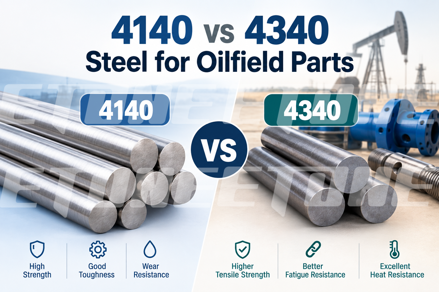
High-pressure backsurge applies severe shear stress across the hinge pin. Generic pins machined from standard carbon steel can bend or shear under pressure cycles. Precision pins manufactured from heat-treated alloy steel (AISI 4140 or 17-4PH) provide the yield strength needed to withstand heavy mechanical shock.
Explosive Decompression of Elastomer Seals
Gas molecules are able to infiltrate ordinary NBR seals during sour‑gas service or high‑pressure gas flowback cycles. Once pressure falls at a fast rate, the captive gas expands forcefully and tears the seal apart. Seal damage from explosive decompression can be avoided by selecting high‑performance HNBR or Viton elastomers certified against Rapid Gas Decompression (RGD).
5. Comprehensive Oilfield Spare Parts Portfolio from Etone Oil
To maintain high-pressure manifold safety across well pads and fracturing sites, Etone Oil (www.etoneoil.com) manufactures a complete line of precision-engineered replacement kits:
Flapper Check Valve Repair Kit: Complete rebuild sets featuring precision CNC-milled flapper plates, hardened hinge pins, high-fatigue torsion springs, and elastomeric seals for 1502/1002 check valves.
Plug Valve Repair Kit: Match-ground side segments, heat-treated plugs, inner/outer seal rings, and grease injectors designed for quarter-turn isolation valves.
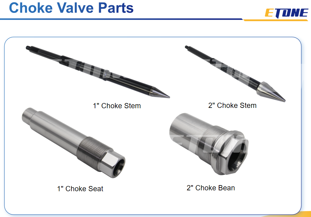
Choke Valve Parts: Tungsten carbide choke beans, adjustable stem needles, and seat inserts for high-velocity flowback manifolds.
Relief Valve Repair Kit: Precision-calibrated relief springs, ground stainless steel discs, and high-temp seats engineered for rapid pressure relief.
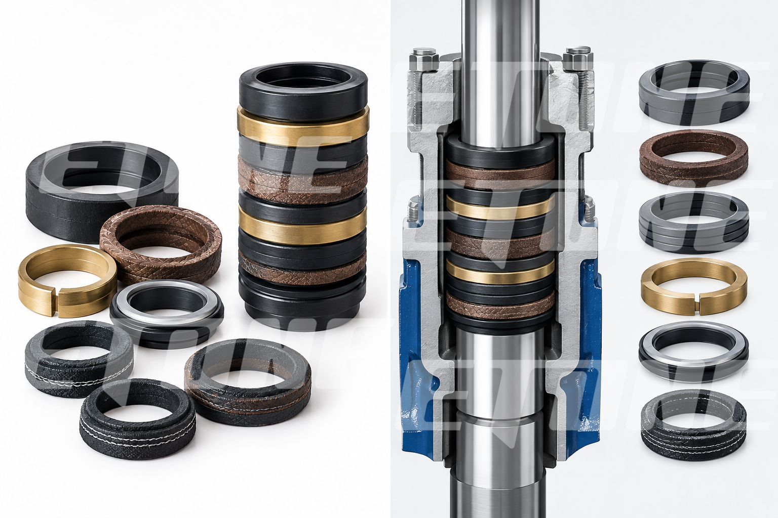
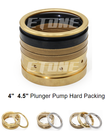
Plunger Pump Packing: Kevlar-reinforced V-packing sets, adapter rings, and header rings for frac pump fluid ends.
Partner with Etone Oil for Reliable Flow-Line Replacement Parts
Proactive field maintenance with precision replacement parts is the most effective strategy to prevent washouts, protect mud pumps, and eliminate unscheduled NPT.
At Etone Oil (www.etoneoil.com), every Flapper Check Valve Repair Kit, Plug Valve Repair Kit, and Plunger Pump Packing set is manufactured under strict quality control standards to ensure 100% drop-in compatibility and long-term field reliability.
Upgrade your high-pressure manifold maintenance today.
Visit www.etoneoil.com to view our full replacement parts catalog, download product specifications, or contact our technical sales team for a custom quote. If you have any questions, please contact us promptly: pe@etoneoil.com