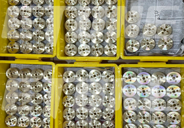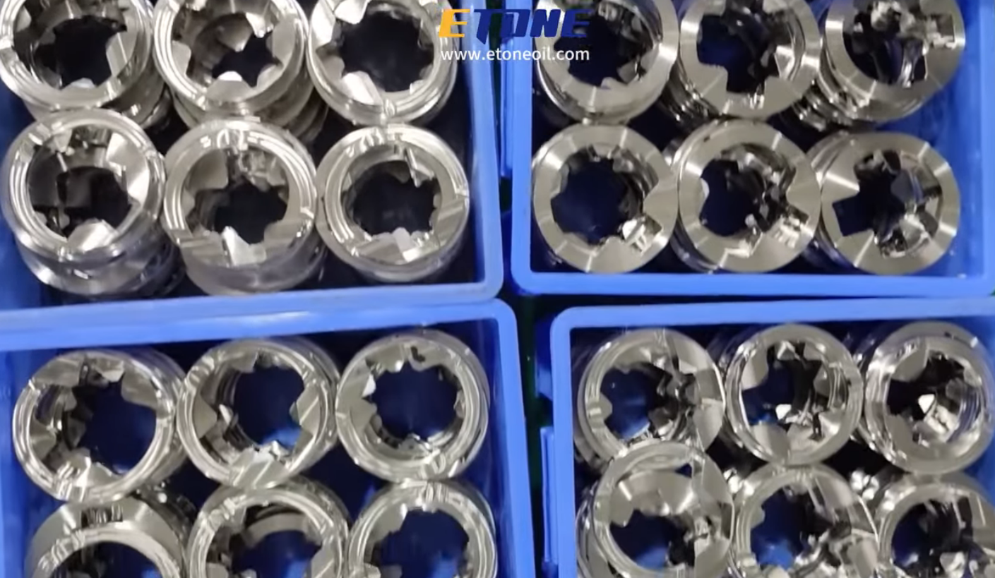
In oil and gas production, I see that wellhead pressure control and flow regulation are essential for safety, reservoir performance, and equipment longevity. At the heart of high‑pressure flow control systems is a critical part: the choke bean. The choke bean is housed inside choke valves or choke manifolds and has a precisely sized internal opening that limits fluid flow, turns static pressure into moving energy, and maintains the best wellhead backpressure. The choke bean operates under pressures from 5,000 PSI to 15,000 PSI (34 to 103 MPa). If the choke bean is not sized correctly or is not replaced on time, the reservoir can sand, fluid can bubble, and the gas‑to‑oil ratio can. Equipment can wear out early.
At Etone Technology, we manufacture and deliver precision-engineered severe-service oilfield spare parts and flow control hardware. In this comprehensive technical sizing guide, we examine the physics of choke orifice selection, mathematical flow rate calculation, wear diagnostics, and replacement protocols for oilfield choke beans.
1. The Operational Role of Choke Beans in Oil & Gas Flow Lines
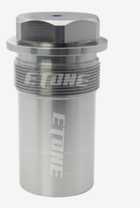
A choke bean serves as the primary fluid restriction mechanism across wellhead trees, frac flowback manifolds, sand separators, and production choke assemblies.
Primary Functions in Wellhead Pressure Management
Reservoir Protection: Prevents rapid reservoir drawdowns that cause formation water coning or sand influx into the wellbore.
Pressure Reduction & Gas-Tight Isolation: Drops line pressure from 15,000 PSI surface pressure to safe operating limits for downstream separators and heaters.
Flow Rate Regulation: Controls daily barrels of oil per day (BOPD) or million standard cubic feet per day (MMSCFD) produced.
Vessel Protection: Protects separators, heater treaters, and transport pipelines from sudden pressure surges during well unloading or slug flow.
2. Standard Choke Bean Orifice Sizing Conventions
In North American international oilfield practices, choke bean orifice sizes are measured in sixty-fourths of an inch (1/64″).
Choke Bean “Size”: This is a number that stands for N/64 inches.
Example: A Size 16 Choke Bean has an internal diameter of 16/64″ = 1/4″ (0.250 in / 6.35 mm).
Example: A Size 32 Choke Bean has an internal diameter of 32/64″ = 1/2″ (0.500 in/ 12.70 mm).
Example: A Size 48 Choke Bean has a diameter of 48/64″ = 3/4″ (0.750 in / 19.05 mm).
3. Materials & Metallurgy for Severe-Service Choke Beans
Fluid moves fast inside the choke bean throat, often going over 300 ft (90 m/s). This high speed, combined with sand from the formation and ceramic proppants, causes rapid erosion. Standard steel inserts don’t last under these conditions. Choosing wear-resistant materials is essential to keep the choke working longer.
Advanced Insert Material Grades
Tungsten Carbide (WC-Co / WC-Ni): This is the go-to material in the oilfield for choke beans. It’s hard (1,500- 2,200 HV) and tough enough to resist cracking. Nickel-bound versions meet NACE MR0175 and ISO 15156 standards for use with gas that contains H_2S.
Silicon Carbide (SiC): A technical ceramic that is extremely hard and completely resistant to acid even across a wide pH range from 0 to 14. It’s best used where there is steady fine sand abrasion but not heavy impact.
17-4 PH Stainless Steel Outer Carriers: The carbide or ceramic orifice sleeves are pressed or brazed into stainless steel bodies. This helps the choke handle the stress during installation.
4. Wear Diagnostics and Choke Bean Replacement Protocols
An eroded choke bean compromises safety and flow accuracy. Field technicians must monitor key indicators to detect orifice enlargement before complete washout occurs.
Step-by-Step Replacement Procedure
Isolate and Bleed Pressure: Close upstream and downstream block valves. Bleed pressure safely from the choke manifold bleed valve.
Unthread Cap / Retainer: Remove the choke valve bonnet or bean retaining nut using specialized wrenches.
Extract Worn Bean: Use a dedicated choke bean-puller tool to extract the tapered bean without scoring internal housing threads.
Inspect Housing Seat: Clean internal seating shoulders and check for body washouts or wireline damage.
Install New Precision Bean: Apply anti-seize compound to external threads, seat the new carbide choke bean, and torque to OEM specifications.
Hydrostatic Verification: Pressurize manifold to verify bubble-tight sealing prior to introducing well flow.
5. Comprehensive Oilfield Spare Parts Portfolio
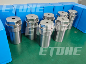
To maintain continuous field operations without non-productive time (NPT), service fleets and rig operators require immediate access to precision-machined replacement hardware built to exact API dimensional standards.
At Etone Technology, we manufacture a broad line of precision replacement parts and severe-service repair kits:
Key Replacement Parts & Repair Kits
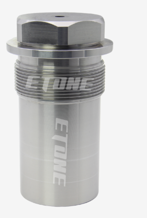
Choke Valve Parts: Solid tungsten carbide and silicon carbide choke beans, choke stems, needle plugs, flow cages, choke seats, and external sleeve assemblies compatible with major OEM valve designs.
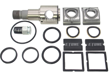
Plug Valve Repair Kits: Complete overhaul kits featuring precision-lapped tapered metal plugs, high-durability sleeves, side segments, elastomeric stem seals, thrust bearings, and dual-check grease fittings rated for 10,000 PSI to 15,000 PSI service.
Flapper Check Valve Repair Kits: Heavy-duty replacement flappers, hinge pins, seats, and torsion springs fabricated from 17-4PH or Inconel alloys for drill strings and choke manifolds.
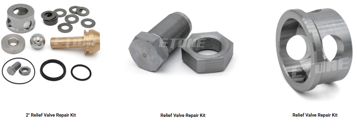
Relief Valve Repair Kits: Exact replacement discs, heavy-duty springs, guide cages, and precision seats designed for accurate set-pressure relief and positive reset.
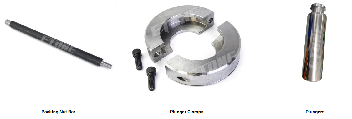
Plunger Pump Packing & Glands: High-durability packing brass, header rings, lantern rings, and V-ring packing sets optimized for reciprocating mud pumps and high-pressure hydraulic fracturing triplex/quintuplex pumps.
6. QA/QQC Standards and Dimensional Inspection
At Etone Technology, every custom choke bean and oilfield replacement component goes through a multi-stage quality control process before it leaves our facility.
Coordinate Measuring Machine (CMM) Verification: This step makes sure that the orifice is perfectly round, that the inner diameter stays within ±0.0005 inches ( ±0.0127 mm), and that the seating angles are accurate.
Sub-Micron Lapping & Surface Polish: The inside walls of the orifice are lapped until they reach a mirror- smoothness (Ra < 0.2 ). This removes flaws that could cause cavitation and reduce performance.
Full Material Traceability: We provide Mill Test Reports (EN 10204 3.1) for all carbide and alloy materials. This gives you proof that the materials meet required mechanical standards.
Partner with Etone Technology for Precision Flow Control Parts
When you are dealing with wellhead flow control, you need a partner who understands metallurgy deeply. You need a partner who can handle multi-axis CNC grinding and who follows strict API-compliant quality control systems.
Email:pe@etoneoil.com
Whether you need sized carbide choke beans, choke manifold repair kits, or replacement parts for high-pressure valves and pumps, Etone Technology has the engineering expertise to deliver dependable solutions. We build parts that are made to last in field conditions.